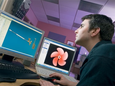
CJR design strategy can be called a holistic approach to the propulsion system. We don’t only make propellers, we analyse the entire propulsion system of each boat starting from hull resistance prediction and hull propulsive factors. We select the most efficient gear ratio, recommend changes if needed and analyse flow in every point under the hull using the most advanced CFD tools developed specifically for our requirements. This approach gives us the widest possible picture of all the possibilities for running your boat more efficiently, quietly, quickly, and any other specific or demanding requirements.
PROPELLER AND STERNGEAR DESIGN PROCEDURE
RESISTANCE PREDICTION
Every propeller enquiry initiates an estimation of the effective power the boat needs to be propelled through the water at certain speeds; resistance prediction plays a big part in it. As a first step, CJR uses quick and reliable prediction software based on regression line developed by Southampton University on the basis of hundreds of tested hulls. A much more sophisticated tool is our Computational Fluid Dynamic (CFD) software that can predict with great detail and show the flow around the hull, pressure field and running trim angle. The latter feature of the program can be used to find the most optimum trim angle for the boat.
OPTIMUM REDUCTION RATIO SELECTION
Having speed prediction of the hull is a natural step forward to selecting the optimum gear ratio that gives the most efficient propeller operation. Gear ratio and engine power govern almost all shaftline parts sizes including propellers, shafts, P-brackets and all associated parts. Gear ratio is a factor that has a huge influence on overall propeller performance.
PROPELLER SIZING
Strictly connected to the reduction ratio, power of the engine and speed of the boat,CJR uses purpose built software based on a number of different propeller series for quick selection of diameter, pitch and number of blades. Lifting line software is utilised for more detailed selection that allows checking blade area requirement due to cavitation. If you would like to read more about lifting surface software please click on the link
STRENGTH AND RULE CHECK
Safety at sea is the most crucial and paramount objective for CJR. Every component designed and built under classification society rules is sized to meet their requirements. CJR in-house software allows for checking of all parts of the sterngear to RINA, BV, LR and many other societies rules. Additionally, propellers blade thickness and stress level can be checked using software based on beam theory taking into consideration nonuniform loading over the blade. This method is approved by most IACS societies and can be used as an alternative to the rules to make propeller blade thinner and more efficient.
Besides Classification Society requirements, newly designed and fit for purpose components are analysed using Finite Element Method software ANSYS, which gives the ultimate picture of component strength under most extreme loads. Please read more about FEA here.
HULL WAKE AND PROPELLER INFLOW
It is the most important information that shows the difference between good and bad propeller design. It can make even decent propellers noisy, vibrating and inefficient. Without knowledge about water inflow to the propeller, every propeller is a guesswork. Using CFD software tailor made to suit planing and displacement crafts CJR introduced propeller wake calculation as a standard procedure. That allows CJR also to optimise propeller inflow by changing shaft brackets design and position or propeller tunnel shape and recommend these changes to boat designer.
FINAL PROPELLER DESIGN
The most advanced vortex-lattice code in propeller market is used to tune propeller final design. Propeller is run by the software in behind hull condition and every blade parameter like chord length, pitch, camber, profile shape can be separately adjusted to the flow to get highest possible efficiency at the propeller design point. Different type of cavitation can be detected on the blade and pressure pulses induced on the hull, the biggest source of noise, are calculated. Propeller model is generated together with pattern model and machine program.
PROPELLER SLIPSTREAM AND RUDDER DESIGN
Rudder area is calculated on the basis of boat size and type, and rudder sections are carefully selected, dependent on flow regime. Purpose built software that couples CFD and propeller code together allows CJR to replicate propeller slipstream under the hull. That is a great advantage in rudder design as detailed inflow velocities is known. Rudder sections will be aligned with the flow to generate minimum drag going on straight line and maximum lift force while turning.
SHAFT BRACKETS AND SHAFTLINE DESIGN
Knowledge about flow around the hull and sterngear allows designing shaft brackets with the least impact on water inflow to the propeller as well as generating lowest possible drag. Location of the bracket and other supporting bearings along the shaftline as well as entire shaftline can also be analysed using Shaft Lateral Vibration Calculation to find out if shaft stresses are within limits under all operation conditions and there is no threat of excessive vibration.
Get in Touch
CJR combines decades of experience with continuous investment in the latest technology and engineering prowess. Just drop us a note to find out more about how we can help you.
CONTACT US